Click the photos for an expanded view
of each. |
|
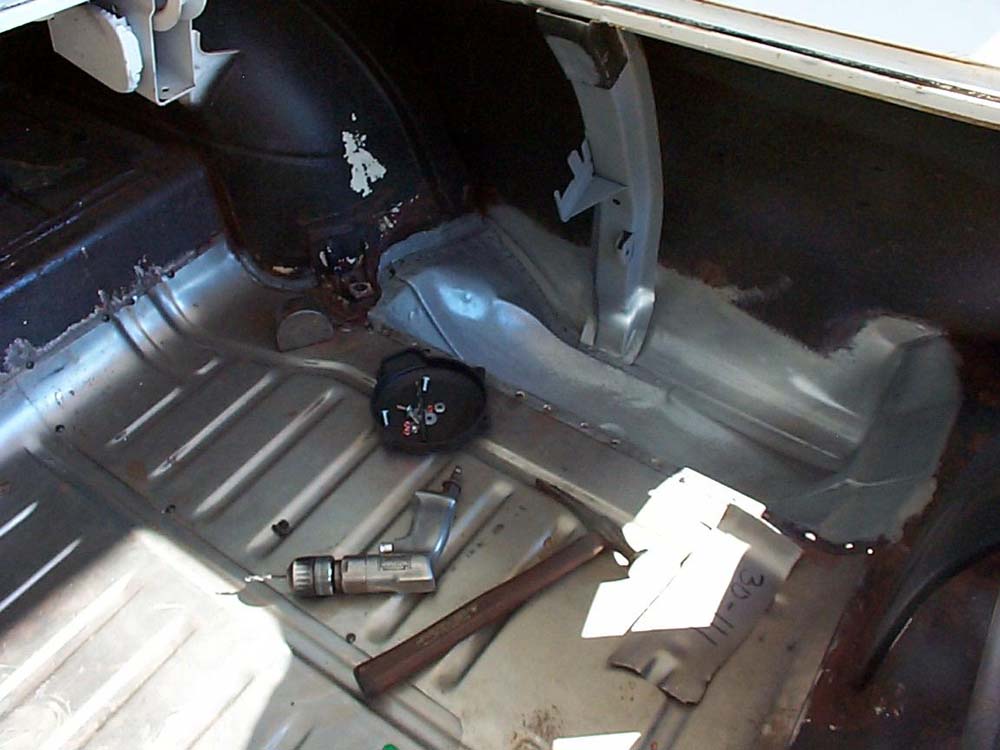 |
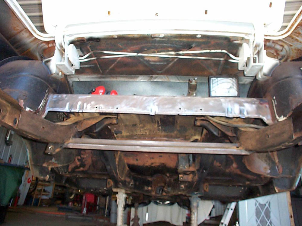
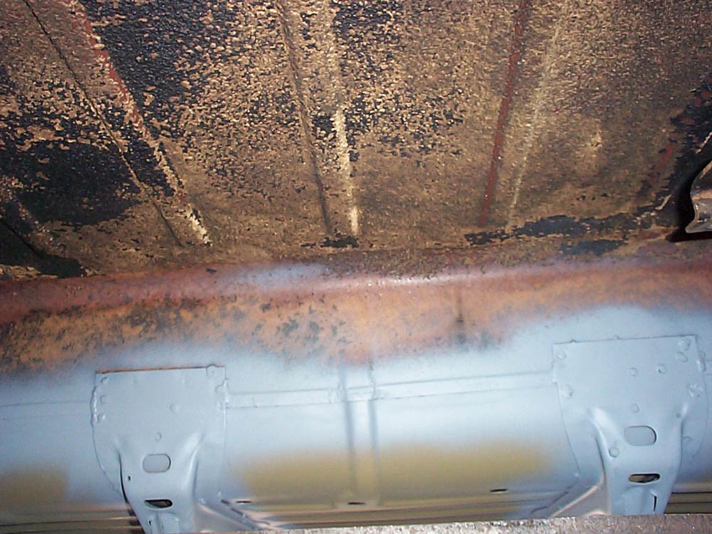
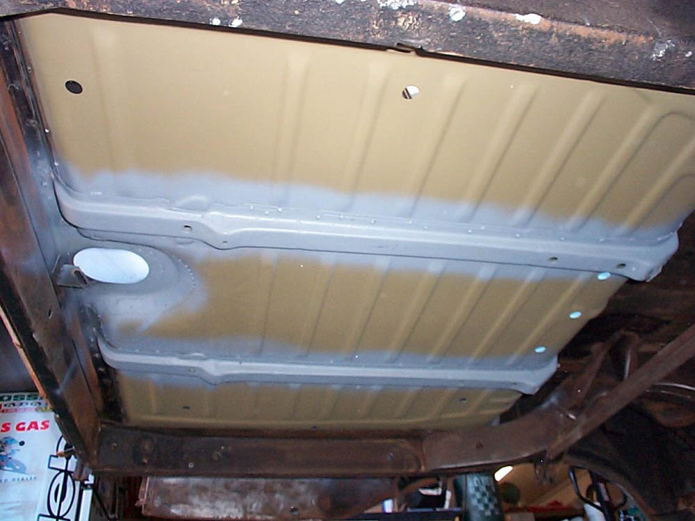
In this photo, one can see the spare tire
mounting brace has been reinstalled, and the areas treated with rust inhibiting
paint. |
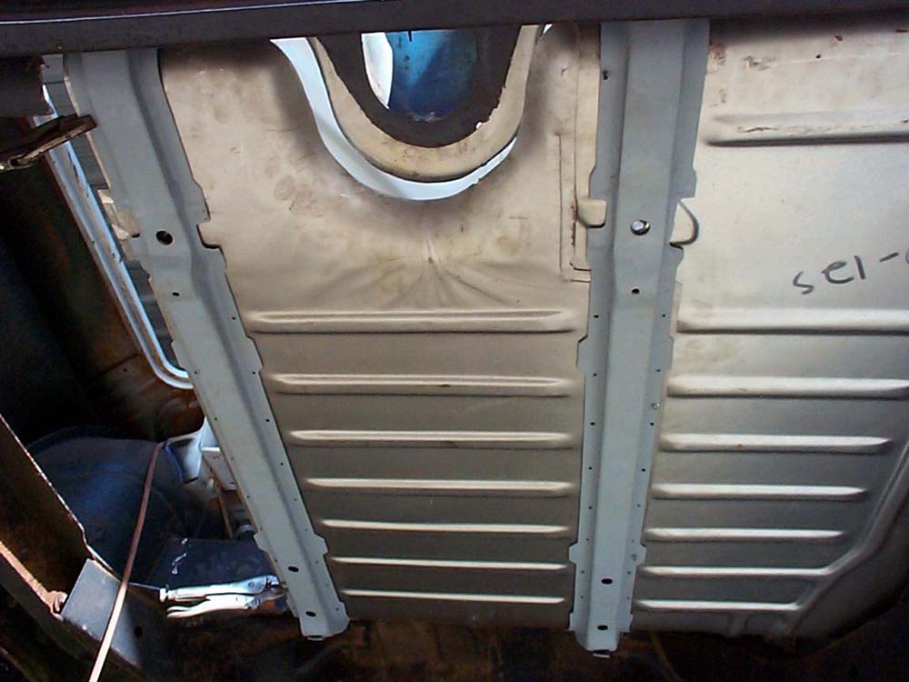
Underside rear view of the trunk floor during test
fitting. |
 |
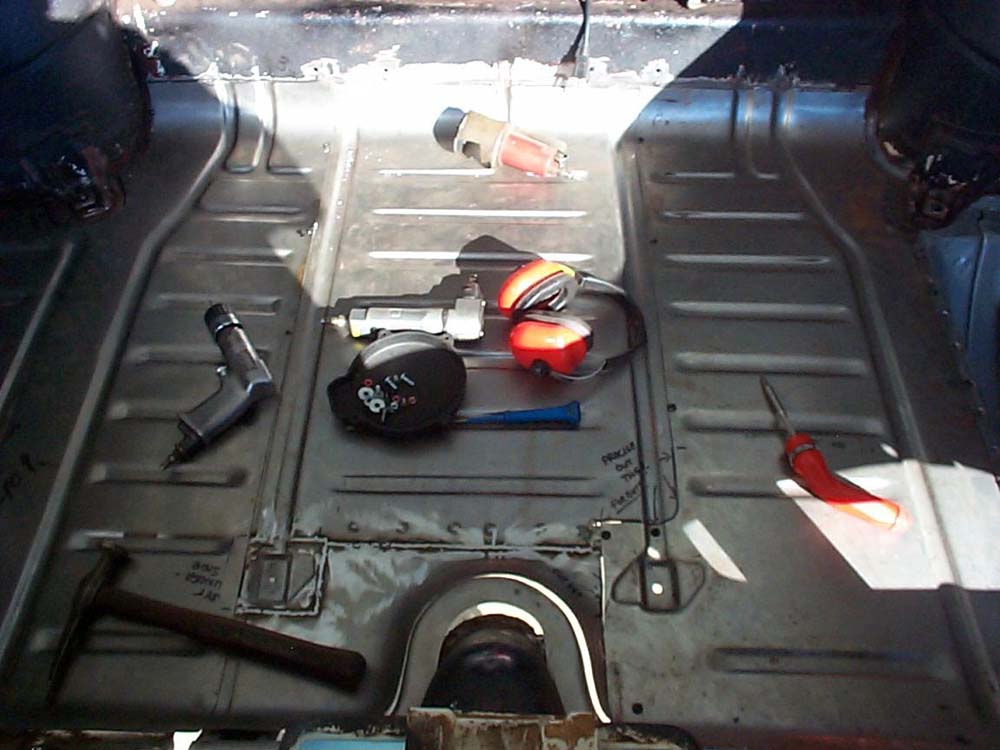 |
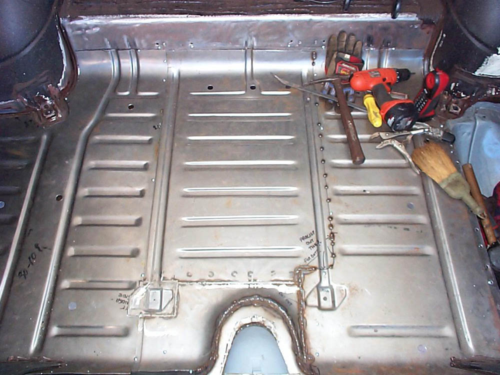
September 28th 2004. The three floor pieces are aligned,
and tack welded together. The aligned assembly can be removed for final
adjustment and fit. |
Final test fitting of the trunk floor at the outer
perimeters. |
 |
 |
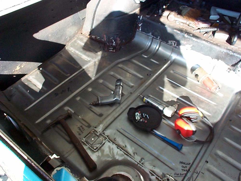
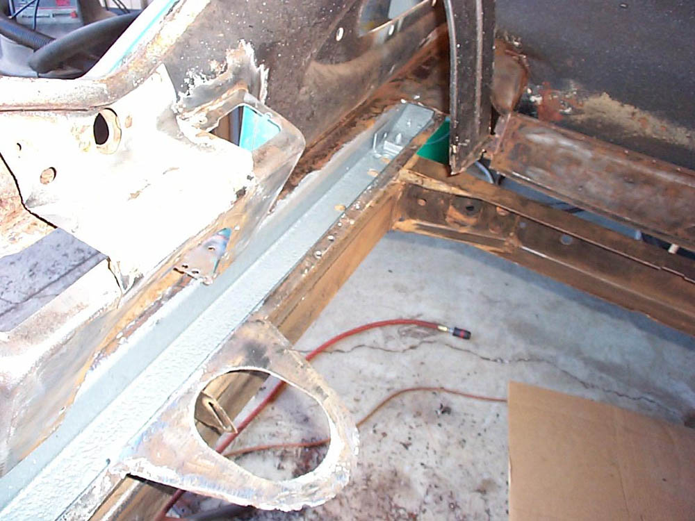
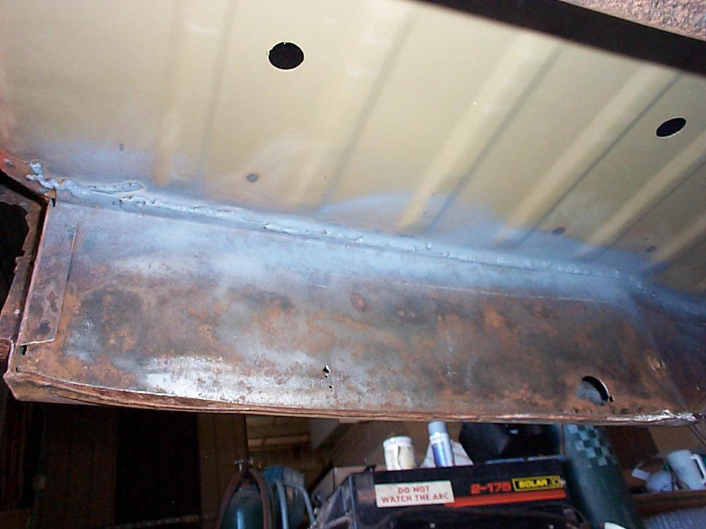
The trunk floor is removed and outside perimeter areas
are prepared for welding. |
The rear floor brace was opened to access this area
for painting with rust inhibitors. |
 |
 |
October 4th 2004. The trunk floor during final welding. |
As three pieces are welded together to form the floor,
a long straight edge is used to check overall flatness of this
area before, and during the final welding stages. |
 |
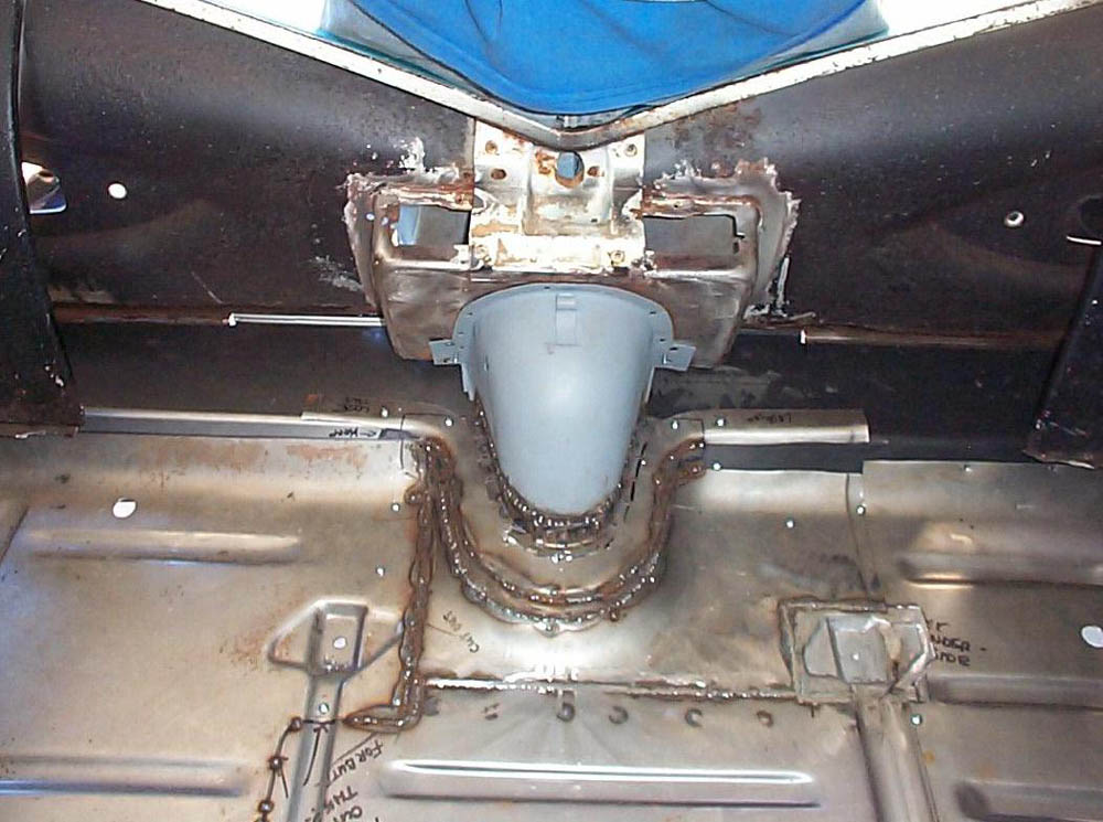 |
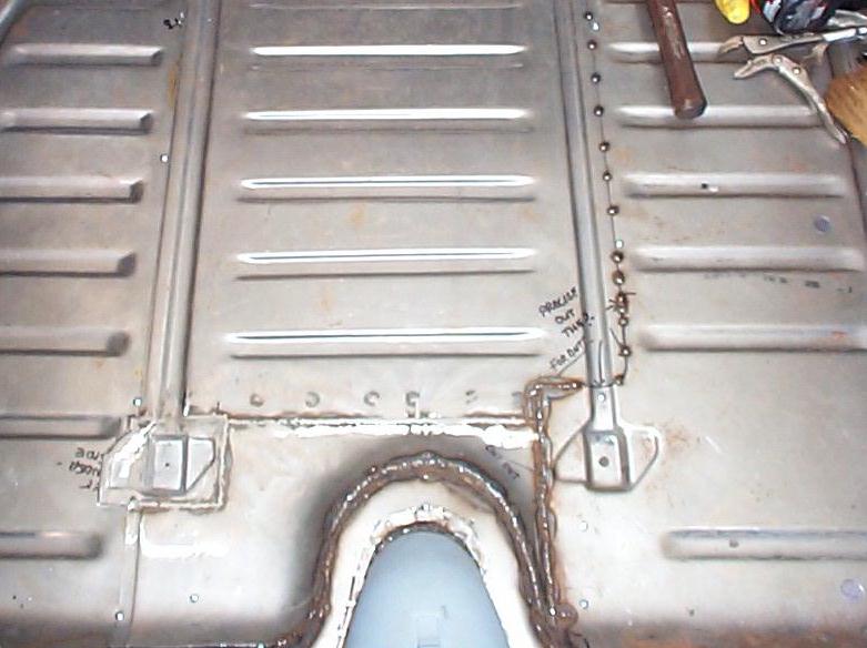
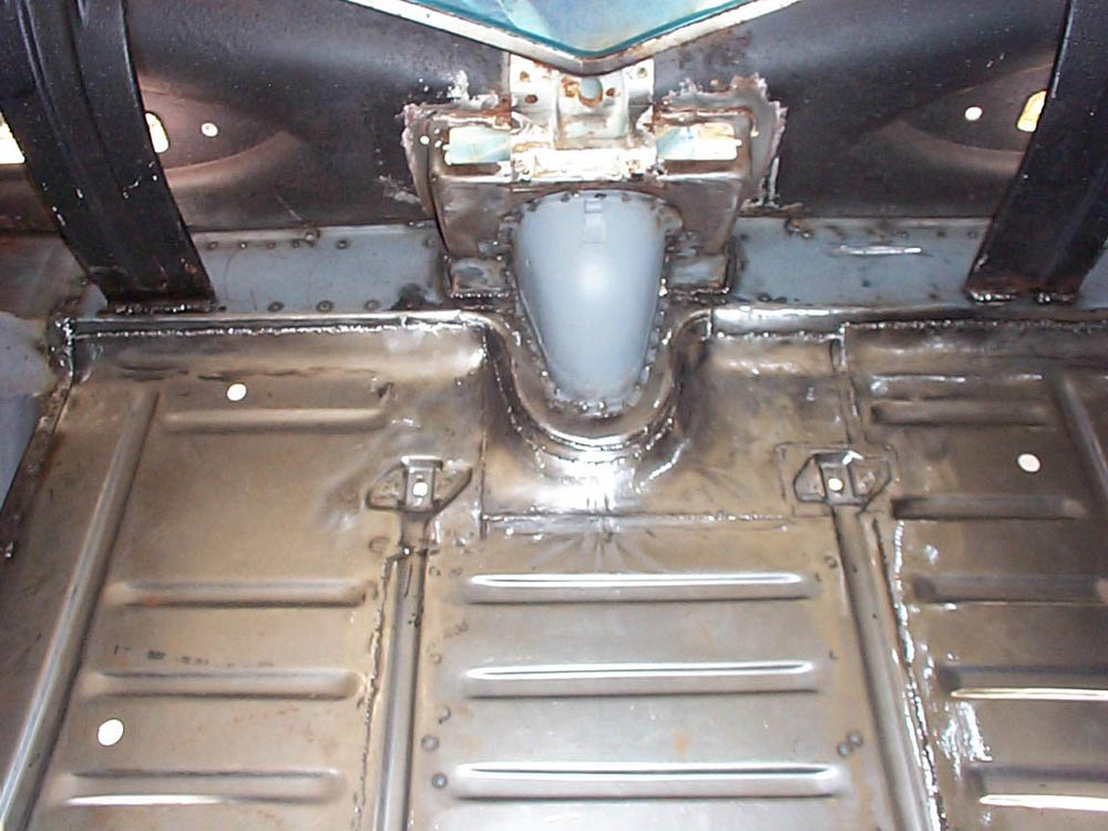
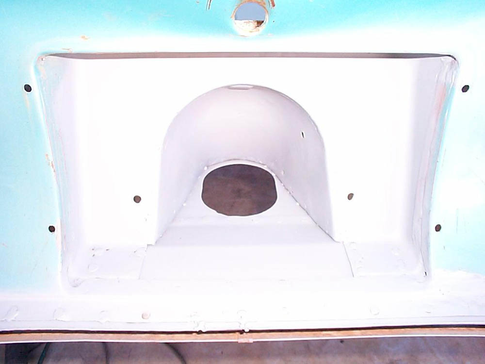
The rear area around the gasoline filler neck was
fabricated as no reproduction parts are available. |
Here we can see the fabricated "step" piece
that raises the trunk floor to the filler neck recess. |
 |
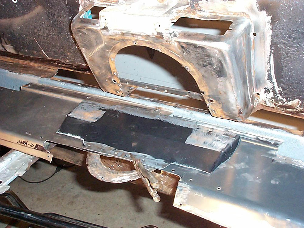 |
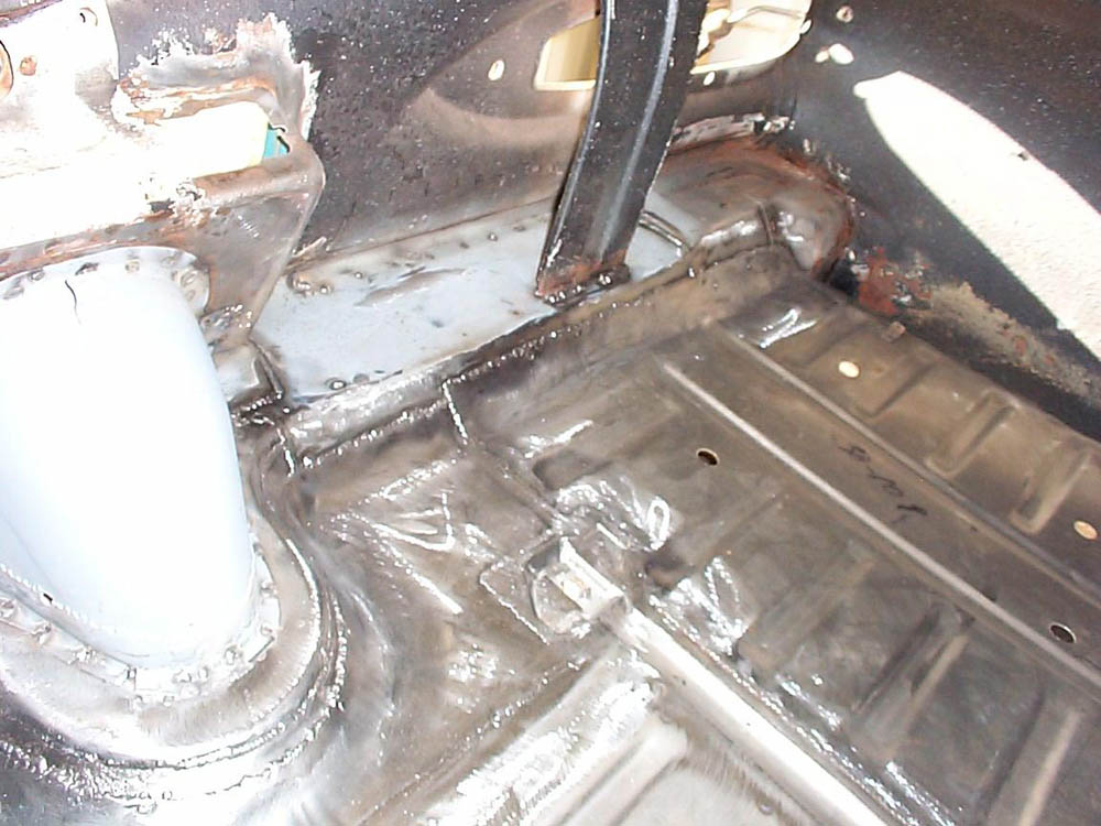
Close up view of the fabricated "step" piece,
and rear floor area that raises the trunk floor to the filler neck recess. |
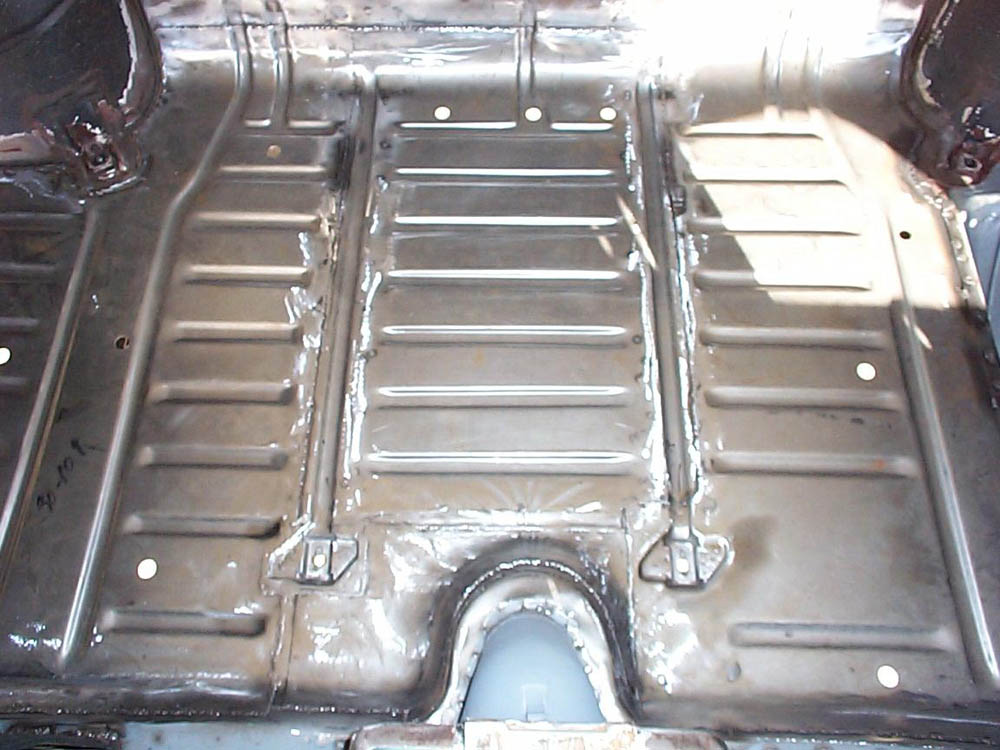
October 6th 2004. Photo of trunk floor after welding
is completed. This trunk floor replacement took approximately 40 metal
work labor hours. Size 0.23 wire was used in the MIG welder to minimize
heat distortion. |
 |
 |
|
 |
|
 |
|
Front view underside |
 |
 |
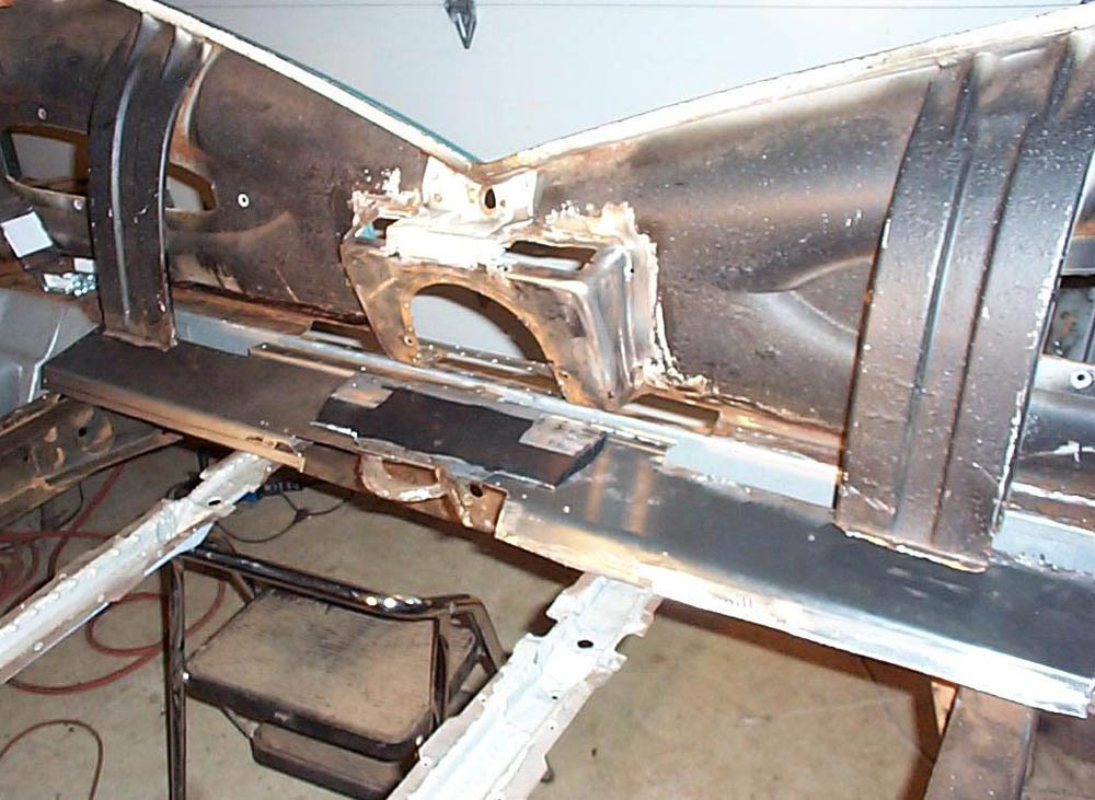
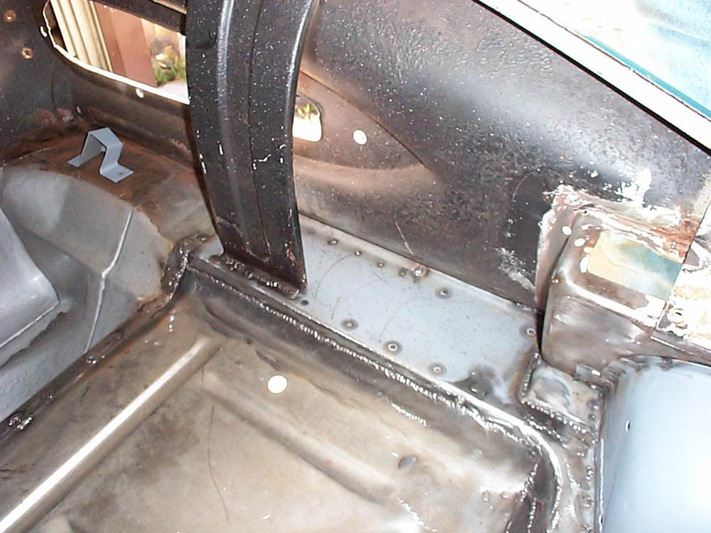
Right side view looking to the left. |
There were perforations in the left rear quarter panel
inner and outer area at the lower rear. This inner reinforcement area
is not reproduced and must be fabricated. |
 |
 |
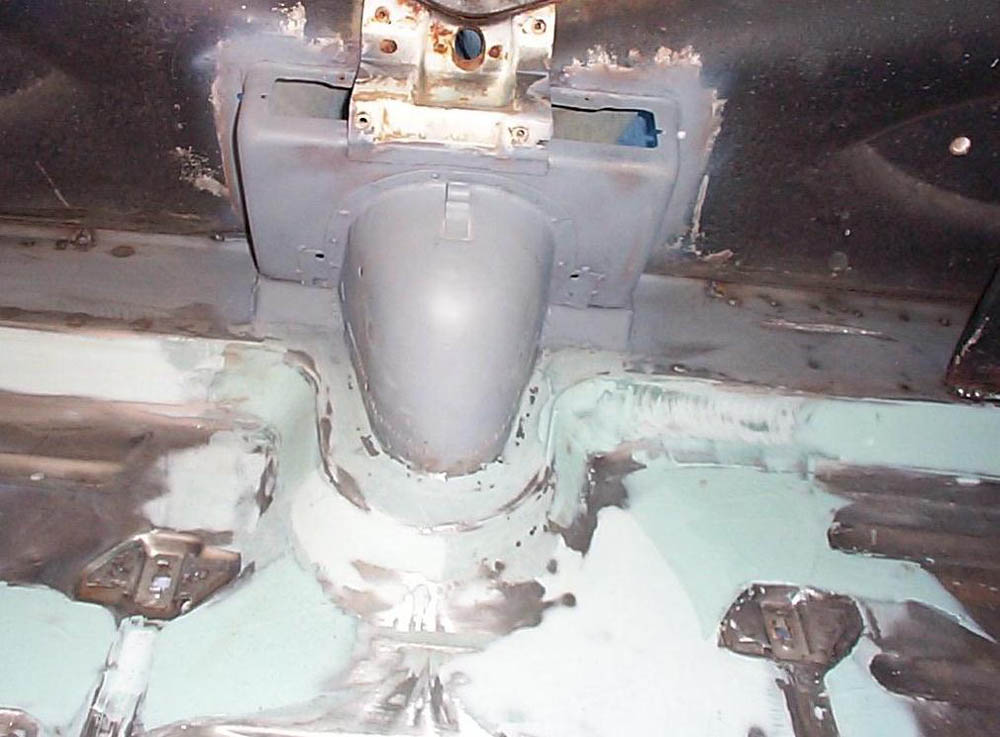
The finished fuel filler neck area viewed from the
outside. |
After surface grinding, a skim coat of waterproof
"duraglass" fiberglass filler was used to smooth out the welded
areas. |
 |
| <Previous 1 2 3 4 5 6 7 Next> | |